

Plastic Recycling Ancillary Equipment
Industrial Air-Cooled Water Chiller
A packaged process-water chiller for extrusion, pelletizing, washing and plastics production. Start from the RT-AWC-15 reference configuration, then configure the cooling circuit, pump, tank, piping, controls and electrical package around the real duty point.
- Approx. 45 kW reference capacity at the listed duty point
- Integrated 12 m³/h circulation loop with 200 L stainless-steel tank
- Cooling duty, refrigerant, voltage, ports and controls engineered to order
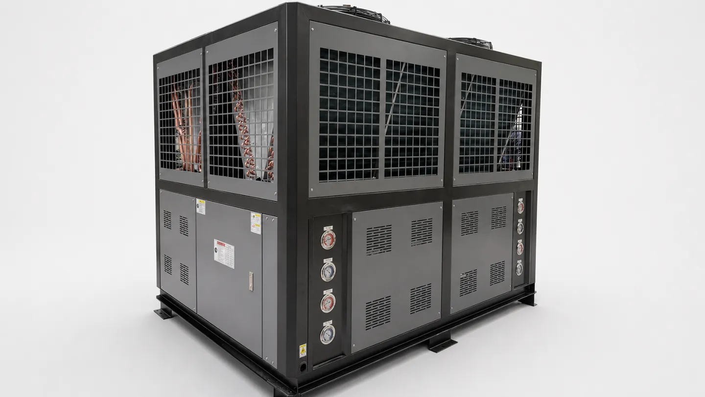
- Approx. 45 kW reference capacity at the listed duty point
- Integrated 12 m³/h circulation loop with 200 L stainless-steel tank
- Cooling duty, refrigerant, voltage, ports and controls engineered to order
Configure the Chiller From the Duty Point
The RT-AWC-15 configuration is a selection reference, not a universal answer. Confirm these five inputs before the final model and component schedule are released.
| Selection Input | RT-AWC-15 Reference | Customize When |
|---|---|---|
| Required cooling load | Approx. 45 kW capacity with a 10°C leaving-water reference | Process heat load, ambient temperature, leaving/return temperature or safety margin differs |
| Water circulation | 12 m³/h flow, 25 mH₂O pump head, 1.5 kW centrifugal pump | Long pipe runs, elevated equipment, pressure-drop limits or multiple users change the system curve |
| Buffer and connections | 200 L SUS304 tank with DN50 inlet and outlet reference | The process requires a different buffer volume, material, port size, open tank or closed pressurized loop |
| Power and controls | 3-phase 380 V, 50 Hz; 14 kW reference input and 28 A reference current | Destination voltage/frequency, remote start, PLC signals, alarms or communication protocol differs |
| Refrigeration circuit | Air-cooled finned condenser and hermetic scroll-compressor architecture | Local refrigerant rules, low-temperature fluid, high ambient, redundancy or corrosion protection requires another package |
Selection note: all listed values are preliminary references. Final capacity, compressor circuit, evaporator type, refrigerant and component schedule are confirmed on the approved project data sheet.
How the Packaged Air-Cooled Chiller Works
The refrigeration circuit removes process heat while the integrated water loop delivers stable cooling water to the production equipment.
Warm process water returns to the tank
Return water enters the packaged loop and is buffered in the stainless-steel tank so short process fluctuations do not immediately destabilize outlet temperature.
The evaporator removes heat from the water
Refrigerant absorbs heat across the selected evaporator. The exchanger type and circuit arrangement are finalized from water quality, temperature range and service requirements.
The air-cooled condenser rejects heat
The compressor raises refrigerant pressure and the finned condenser transfers heat to ambient air through axial fans, avoiding a separate cooling tower loop.
The pump returns controlled cooling water
The centrifugal pump sends conditioned water back to the process. Temperature, phase, pressure, overload and low-water protections supervise the package.
A Standard Package With Project-Specific Engineering
The standard configuration shortens specification work while the interfaces that affect real cooling performance remain configurable.
Packaged Water Circuit
Pump, buffer tank, controls and refrigeration circuit are integrated into one equipment package for simpler plant connection.
No Cooling Tower Required
Air-cooled heat rejection reduces external water-system equipment and is practical where tower water is unavailable or undesirable.
Multi-Circuit Reference Architecture
The reference configuration uses staged compressor capacity so cooling output can follow process demand more closely than a single on/off circuit.
Site-Specific Interfaces
Power supply, piping, refrigerant, communication, corrosion protection and low-temperature options can be matched to the destination plant.
Typical Process Cooling Applications
Use a packaged chiller where production stability depends on controlled water temperature rather than uncontrolled plant-water conditions.
Pelletizing and Extrusion Lines
Stabilizes strand baths, pelletizers, gearboxes or process zones that require controlled cooling-water temperature and flow.
Plastic Washing and Recycling Systems
Supports process-water temperature control where washing, separation or downstream conditioning needs a repeatable thermal window.
Injection and Blow Molding
Provides closed-loop cooling for molds, hydraulic systems and auxiliary equipment when cycle consistency matters.
Industrial Process Equipment
Suitable for reactors, presses, material-production equipment and other users after the actual heat load and utility conditions are verified.
RT-AWC Series Reference Selection Data
Only the main selection values are shown. They are preliminary references for model comparison and utility planning, not guaranteed project performance.
| Selection Item | RT-AWC-15 Reference | Customization Note |
|---|---|---|
| Reference model | RT-AWC-15 | Final model follows the verified cooling duty |
| Cooling capacity | Approx. 45 kW at the stated reference condition | Re-rated for water temperature and maximum ambient |
| Leaving-water temperature | 10°C reference | Lower temperatures or glycol require separate selection |
| Water circulation | 12 m³/h; 25 mH₂O; 1.5 kW pump | Flow and available head follow the actual system curve |
| Electrical supply | 3PH–380 V–50 Hz; approx. 14 kW input | Voltage, frequency and controls can be configured |
| Tank and connections | 200 L SUS304 tank; DN50 reference ports | Volume, material, port size and orientation are customizable |
| Reference dimensions | 1900 × 920 × 1850 mm | Final envelope follows the approved configuration |
| Reference weight | Approx. 900 kg | Confirm shipping and operating weight on the approved drawing |
Reference values are for preliminary selection only. Final cooling capacity, components, dimensions, power, water circuit and refrigerant are confirmed on the project-approved technical data sheet.
Information Required Before Chiller Selection
Cooling capacity alone is not enough. Send these inputs so the chiller, pump and tank are selected as one process-water system.
Process Heat Load
Provide the equipment heat-rejection value in kW or the material throughput, inlet temperature and required cooling result used to calculate it.
Water Temperatures
State required leaving-water temperature, expected return-water temperature and acceptable temperature stability.
Flow, Head and Piping
Share required flow, elevation, pipe length, fitting count, process pressure drop and whether one chiller serves one or several users.
Fluid and Water Quality
Confirm clean water, glycol concentration or other process fluid, plus contamination, corrosion and freezing risks.
Site Conditions
Provide maximum ambient temperature, indoor or outdoor installation, altitude, ventilation constraints and available service clearance.
Electrical and Control Interface
Confirm voltage, frequency, local compliance, remote start/stop, dry contacts, PLC communication and redundancy expectations.
Nominal-Size Quote vs. Verified Duty Selection
A reliable chiller proposal ties every major component to the same operating point instead of selecting from horsepower class alone.
| Decision Point | Nominal-Size-Only Quote | Project-Specific Chiller Selection |
|---|---|---|
| Cooling capacity | Uses “15 HP” or one catalogue kW value as the answer | Rates capacity at the required leaving/return temperature, ambient condition and fluid |
| Hydraulic circuit | Lists a pump model without the external system curve | Checks flow, static lift, process pressure drop, internal loss, tank volume and connection size |
| Refrigeration package | Copies one compressor, evaporator and refrigerant schedule | Confirms circuit count, exchanger type and locally compliant refrigerant for the duty |
| Site integration | Assumes standard voltage, ambient and local control | Matches power, ventilation, remote I/O, alarms, installation clearance and destination rules |
| Approval basis | Treats a quotation table as final performance proof | Issues an approved data sheet, component schedule and layout after engineering confirmation |
Industrial Air-Cooled Chiller FAQs
Is RT-AWC-15 the only available size?
No. RT-AWC-15 is the standard reference configuration shown on this page. The selected RT-AWC model changes with verified cooling load, water temperature, ambient condition, flow, pump head and site power.
Does 15 HP always equal 45 kW of cooling?
No. Horsepower class and cooling capacity are not interchangeable. Actual cooling capacity changes with evaporating temperature, condensing temperature, ambient condition and fluid temperature, so the duty point must be stated.
Can the chiller use a different voltage or refrigerant?
Yes, subject to engineering review. Voltage, frequency and refrigerant should follow the destination country, component availability, operating temperature and environmental regulations.
Is the pump head fully available to the plant?
No. Available external head is the pump head after subtracting the pressure loss inside the chiller. The complete piping system curve must be checked before pump selection.
What protection functions are included in the reference package?
The reference configuration includes low-water-temperature, phase-sequence, high/low pressure, compressor overload/overheat, pump overload, low-water-level and short-circuit protection. Final alarm logic is confirmed in the electrical schedule.
Need the Standard Package Adjusted to Your Process?
Send the required cooling load, leaving and return temperatures, flow, pump head, fluid, ambient temperature, voltage and control interface. Rumtoo will return a project-specific chiller configuration instead of a nominal-size-only quote.